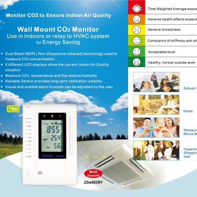
| |
|
|
| |
ZGw063 SERIES - ZGw063 / ZGw063-F |
|
|
|
| |
|
|
 |
3 LED Display:
|
< 800 ppm |
 |
800~1200 ppm |
 |
> 1200 ppm |
|
|
|
|
|
| |
| ZGw063 / ZGw063-F |
 |
| A. Main LCD Display |
B. Green LED Display |
C. Yellow LED Display |
| D. Red LED Display |
E. Mode Button |
F. Up Button |
| G. Down Button |
H. Enter Button |
I. Screw Position |
| J. Power Inlet |
K. RJ 45 Socket
(For factory use only) |
L.Gas Entry Hole |
|
|
|
|
| |
|
|
| |
|
|
|
| |
|
|
|
| |
|
|
|
|
NDIR ( Non-Dispersive-Infrared) technology used to measure CO2 concentration |
|
Three different LED display show the current Indoor Air Quality situation |
|
Reliable Sensor provides long-term calibration stability |
|
Visual and audible alarm function can be adjusted by the user |
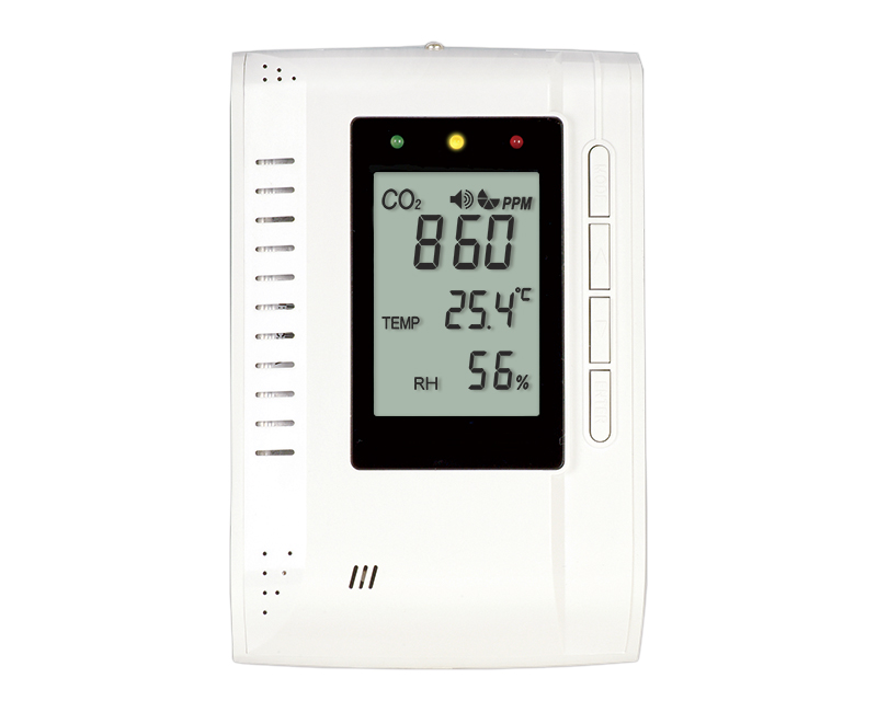
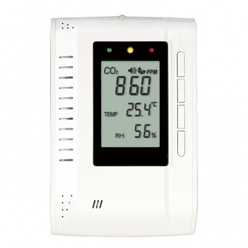
|
|
|
|
|
| |
|
|
|
| |
|
|
|
| |
|
|
|
| |
 |
Warning : Your safety is very important to us. To ensure to use the product correctly and safely, we would like |
| |
to draw your attention to read the warning labels and the User Manual before using the product. |
| |
These are important safety information and should be observed at all times. |
1. |
Please handle the device lightly; do not subject the product to impact or shock. |
2. |
Do not immerse the product in water. |
3. |
Do not touch the exposed electronic circuitry of the device under any circumstances. Keep the circuit closed |
|
during installation, as there is the danger of electric shock. |
4. |
Please use only the included power adaptor. Improper power adaptors or power sources can cause serious |
|
damage to the product, or result in injury or death to the user. |
5. |
Do not keep the product under hot and/or extremely moist environment. |
|
Keep the product away from any heat source or near water. |
6. |
Please ensure the screws are fixed on the wall tightly. Do not let the screws approach or close to the surface |
| |
of PCB board during installation. It has the risk of circuit damage or irreparable damage to devices. |
|
|
|
|
| |
|
|
|
| |
|
To ensure to receive maximum benefit from using this product, please observe the follow guidelines. |
1. Cleaning ---- Disconnect the power before cleaning. Use a damp cloth; do not use liquid cleaning agents, such as benzene, thinner or aerosols. |
2. Repair ---- Do not attempt to repair the product or modify the circuitry by yourself. Please contact the local dealer or a qualified repairman if the product needs servicing. |
3. Calibration --- Please observe the calibration operation to make sure the accuracy for the device when necessary. |
4. Air circulation --- The vents allow the air circulation liquid for measurement of the CO2 concentration and the ventilation should not be blocked. |
|
|
|
|
| |
|
|
|
| |
 |
Before installation, please carefully take out all parts from the package. |
| |
 |
 |
 |
 |
 |
| Step 1 |
Step 2 |
Step 3 |
Step 4 |
Step 5 |
|
|
Step 1: Release the screw from the device by screwdriver, and take the front cover off. |
|
Step 2: Release the four screws from the back cover, take the CO2 board from the back cover. |
|
Step 3: Use the screwdriver to fix the back cover to the wall with screws. |
|
Step 4: Re-assemble the CO2 board by screws to the back cover, and Install the front cover to the CO2 board |
|
after the CO2 board is fixed well. |
| |
Step 5: Tighten the Front Cover screw with screwdriver. |
| |
Step 6: Connect the AC adapter with the power inlet. |
 |
Caution: |
The RJ45 socket is only for factory calibration use, not for LAN, it was covered by plastic cover, the |
| |
|
incorrect RJ 45 connection will have the risk of circuit damage or irreparable damage to devices. |
|
|
|
|
| |
|
|
|
| |
When the power has been connected, The ZGw063 CO2 monitor will begin to work. In order to meet your
personal requirements, it is advisable to set up the customizing parameters.
WarmUp:
It lasts approximately 1min before WARM UP disappears; all MODE functions will not response during warm up.
| Temperature (ºC/ºF) and Ventilation Rate: |
 |
- Press up/down to select the temperature and ventilation rate modes.
- When pressing up button, the LCD display sequence is Temp ºC -> Temp ºF -> Vent Rate l/p/s -> Vent Rate cfm/p. When pressing down button, The LCD display sequence is reverse.
|
Using the MUTE function: |
 |
- Press MODE, the MUTE icon flashes simultaneously.
- Press ENTER, use up/down to select the on/off.
- Press ENTER again to save the data.
|
Note: The factory setting with alarm is buzzer off, user can set the alarm on/off according to MUTE function
instruction. |
Setting the ALTI mode: |
 |
- Press MODE, the ALTI icon flashes.
- Press ENTER, ALTI show on the display And press the mode button to alter between the m(meter) and ft (feet).
- Adjust altitude (step=100m/500ft) by up/down button.
- Press ENTER again to save the data.
|
Setting the ALARM 1 level: |
 |
- Press MODE, the ALARM 1 icon flashes.
- Press ENTER. Using the Up/Down to set the parameter. the default alarm 1 is 800 ppm.
- Press ENTER again to save the data.
|
Note: 1) When the CO2 Alarm level is ≧1,000 ppm, the interval is ±100ppm, when the CO2 Alarm level is <1,000 ppm, the interval is ±50 ppm.
2) After setting with new alarm level parameter, the green LED will light when CO2 concentration below the alarm 1 level. |
Setting the ALARM 2 level: |
 |
- Press MODE, the ALARM 2 icon flashes.
- Press ENTER. Using the Up/Down to set the parameter. the default alarm 2 is 1200 ppm.
- Press ENTER again to save the data.
|
|
*Note: 1) When CO2 Alarm level is ≧1,000 ppm, the interval is ±100ppm, when the CO2 Alarm level is
<1,000 ppm, the interval is ±50 ppm.
2) After setting with new alarm level parameter, the green LED will light when CO2 concentration below the alarm1 level. The red LED will light when CO2 concentration exceeds the alarm 2 level, the yellow LED will light when CO2 concentration is between the alarm1 level and the alarm 2 level. |
Setting the OUTSIDE Mode: |
 |
- Press MODE, The OUTSIDE flashes.
- Press ENTER, shows OUTSIDE,CO2 and ppm flashes. Press the Up/Down to adjust the reading.
|
Note: Ventilation rate represents how much air is introduced into the indoor space from outside. Low
numbers indicate low ventilation rates and potentially, poor air quality. High levels indicate excessive
ventilation and potential excessive energy usage. To obtain an accurate measurement, reading should be taken 2~3 hours after occupancy has stabilized in a space or at a peak in daily CO2 concentrations.
For indoor air quality control, CO2 value is an indicator of ventilation rate. 400ppm (Parts Per Million) is the default CO2 concentration outside (according to ASHRAE: American Society of Heating, Refrigeration and Air conditioning Engineers) |
Setting the MAX MIN Model: |
 |
- Press MODE, the MAX MIN flashes simultaneously.
- Press ENTER, the reading of CO2 and Temperature shows on the LCD alternatively.
- Press Up/Down and the “CLR” will flash on the LCD. Press Enter to CLEAR the MAX and MIN record.
|
Note: With the Built-in MAX MIN mode, ZGw063 can provide the Maximum and Minimum CO2,temperature
reading record after the device is powered on. If users press up/down to clear the MAX and MIN CO2,
temperature reading record, ZGw063 will provide the new MAX and MIN CO2 ,temperature reading
from that time. |
Setting the CALI (calibration) Mode: |


|
- Press MODE, The CALI flashes.
- Press ENTER, the CALI icon on the display. Adjust the lower display to the ambient CO2 reading by Up/Down button.
- Press MODE for more than 10sec, CALIBRATION flashes. Calibration will be done automatically after 3 minute and the LCD will display “Pass” or “Fail.” If it shows “Fail,” please try again.
|
Setting the DataloggerMode: |
 |
- Press MODE, DATALOGGER icon flashes.
- Press ENTER, the reading of CO2 and Temperature shows on the LCD.
- Press Up/Down to page up/down the reading. The numbers from 1 to 48 will display with CO2 reading alternatively. If the LCD display with number “1”, it indicates the first datalogger with CO2, temperature reading.The datalogger function can record 48 sets reading.
|
|
Setting the "RcFS" Mode: |
 |
- Press MODE, The rcFS flashes simultaneously.
- Press ENTER, the icon “no” shows on the LCD, Press the Up/Down to select the no/yes.
- After selecting, press ENTER to save the changes.
|
Note: If the users set the data or calibrate the sensor wrongly. You can use the RscFS (Recover the factory Setting) to come back to factory setting data. |
|
|
|
| |
|
|
| |
| |
Method - NDIR |
| |
Sample Method -Diffusion or flow through (50 ~200 ml/min) |
|
|
| |
| CO2 Specification
|
| Measurement Range |
0~3,000ppm |
| Display Resolution |
| 1ppm at 0~1,000ppm; |
| 5ppm at 1,001~2,000ppm; |
| 10ppm at 2,001~3,000ppm |
|
| Accuracy |
0~2,000ppm, ± 70 ppm or ±5% of reading whichever is greater; over 2000ppm: +/-7% |
| Repeatability |
±20 ppm @400ppm |
| Temperature Dependence |
ZGw063:
±0.2% of reading per °C or ±2 ppm per °C, whichever is greater, referenced to 25°C
ZGw063-F:
±0.2% of reading per°C or ±2 ppm per°C, whichever is greater, referenced to15°C - 35°C.Otherwise ±0.4 % of reading per °C or ±4 ppm per°C at other temperature range,whichever is greater, referenced to 25°C |
| Pressure Dependence |
0.13% of reading per mm Hg
(Corrected via user input for altitude) |
| Response Time |
<2min for 90% of step change |
| Warm-Up Time |
<60 seconds at 22°C |
| Zone LED Display |
Green:<800ppm, Yellow:800~1200ppm, Red: >1200ppm |
| Power Supply |
6VDC AC adapter |
| Storage Temperature |
-20°C to +60°C(-4°F to 140°F) |
|
| Temperature specification |
| Temperature Range |
Display 0°C to 50°C( 32°F to 122°F) |
| Display Resolution |
0.1°C(0.1°F) |
| Display Options |
°C / °F |
| Accuracy |
±1°C(±2°F) when the fan blows to the device directly, the accuracy of temperature is +/- 1.5 degC |
| Response Time |
20-30 minutes (case must equalize with environment) |
|
General Operating Conditions |
| |
Operating Temperature: 0-50°C (32-122°F) 0-95% RH, non-condensing |
| |
Storage Temperature: -20 to 60°C ( -4 to 140°F) |
|
| Dimensions |
|
Weight
(including batteries) |
|
Calibration & Warranty |
Notice: |
Before calibrating, you need to obtain standard gas or semi-standard gas, there |
| |
are 3 ways to get standard gas. |
|
| |
Method A: use CO2 in office/building |
| |
- |
Use two meters (One is the device for calibration. The other one is a calibrated |
| |
(new) one. |
| |
- |
Use ambient room gas for calibration in office, waiting at least 10min, until the CO2 reading doesn’t change |
| |
| |
(Notice: user must not breathe toward the ZGw063, CO2 from the user will affect the reading of ZGw063) |
| |
| - |
Use the reading of the new device as the standard reading. |
| - |
Calibrate device by the Cali Mode instruction. |
|
| |
Method B: use CO2 outsides |
| |
- |
Use ambient room gas for calibration outside. Wait at least 10min, until the CO2 |
| |
reading stabilizes. |
| |
(Notice: user must not breathe toward the ZGw063, CO2 from the user will affect |
| |
|
the reading of ZGw063) |
| - |
Use 380~420ppm as the standard reading. |
| - |
Calibrate the device by the Cali Mode instruction. |
|
| |
Method C: use standard CO2 in the bottle |
| |
- |
Pump the standard CO2 gas(0~1000ppm, flux = 0.1~0.2 liter/min) into the |
| |
ZGw063 from the Gas Entry Hole, waiting about 2~3min. |
| |
- |
Calibrate the device by the Cali Mode instruction. |
|
|
|
| Fault Codes & Troubleshooting Guide |
This section includes a list of Frequently Asked Questions for problems you may encounter with the ZGw063 CO2 Monitor. |
|
No. |
LCD Fault Icon |
Description
(of the fault) |
Indication |
Suggested Actions |
| 1 |
Er3 |
| |
The ambient temperature has exceeded the temperature range 0°C to 50°C ( 32°F to 122°F) |
|
“Er3” flash |
| |
This error will disappear when the temperature returns to the range between 0°C and 50°C
( 32°F to 122°F) |
|
| 2 |
Er4 |
Some wrong measurement or the sensor has exceeded its expected life |
“Er4” flash |
| |
Please wait when CO2 reading recover after around 30 minutes, if “Er4” still appears, please unplug the AC adapter and reconnect it.
If the “Er4” always appears, please contact with the local dealer. |
|
| 3 |
Er5
Er6 |
EEPROM System Problem |
“Er5”
&
“Er6”
flash |
| |
Please unplug the AC adapter and reconnect it.
If the “Er5,Er6” always appear, please contact with the local dealer. |
|
| 4 |
Er7 |
Internal Data Transmission Error |
“Er7” flash |
| |
Please unplug the AC adapter and reconnect it. |
|
|
|
|
|
|
|
| |
|
|
| |
Kinds of Adapters for your option
(Only for ZGw08PR)
|
ACAeu |
|
including |
German、Italy ) |
|
|
|
|
including |
Singapore、 |
BS1363 ) |
|
|
|
|
|
|
|
|
|
Available Packages
|
|
| |
White Box Size: |
| |
158.5(L)* 158(W)*48 (H)mm |
| |
One Set Included: |
| |
|
1 CO2 Monitor |
| |
|
1 Power Adaptor |
| |
|
1 User Manual |
| |
|
1 White Box |
| |
|
2 screws |
| |
One Carton Included: |
| |
|
Q'ty: 30pcs PaperBoxes |
|
| |
|
Carton Size: |
| |
|
495*465*275mm; 2.23 Cube ft |
| |
|
|
| |
|
N.W: |
| |
 |
EU Spec. Power Adaptor : 11.1 kgs |
| |
 |
U.S Spec. Power Adaptor: 10.95 kgs |
| |
|
|
| |
|
G.W: |
| |
|
EU Spec. Power Adaptor : 12.4 kgs |
| |
|
U.S Spec. Power Adaptor: 12.25 kgs |
|
|
|
|
|
|
|
|
|
|